


Start with the roof and the complete support system
Metal building solar panels require coordinated review of roof condition, mounting, structural loads, water management, electrical work and warranty requirements. A panel's weight per square foot is not a complete feasibility test. Follow the forces from the array through attachments, roof components, secondary framing, primary framing and foundations, and establish who evaluates each interface before the layout is approved.
The MBMA retrofit guide says solar additions require review of roof systems and primary and secondary members, and can introduce wind and snow effects as well as added weight. It also calls for review of mounting integrity and possible roof-warranty impacts. This supports a system assessment, not a universal reinforcement requirement.
Begin with the project objective and roof history. Is this a new building being designed with a known array, an existing roof with complete drawings, or a roof whose condition and details are uncertain? The evidence and sequence differ. A new project can coordinate interfaces before fabrication, while a retrofit may need investigation before the solar contractor can select a suitable attachment.
This guide uses an interface chain: roof identity and condition, load path, mounting compatibility, water and movement details, construction access and future service. It does not provide clamp spacing, fastener schedules, electrical installation instructions or a return-on-investment claim. Those require the actual products, site, design and commercial terms.
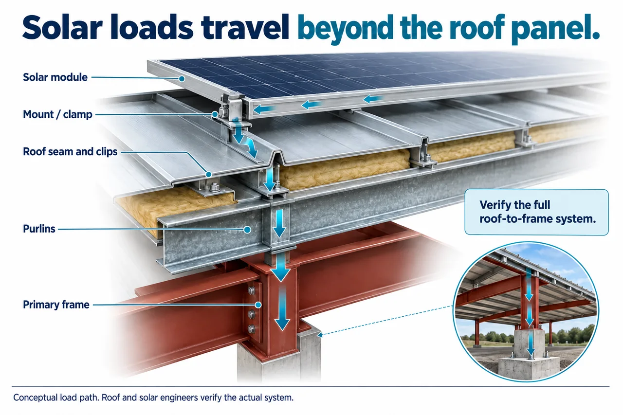
Trace the array loads beyond the metal panel
Draw the intended path from module to mounting hardware, roof connection and supporting structure. Identify where an attachment transfers force into a seam or fastener, how the roof is supported and which members carry the reaction onward. A mount's published capability does not automatically establish the capacity of every part below it.
Distinguish distributed array weight from forces at individual supports. A light average load can still produce attachment reactions that need evaluation. Wind can introduce forces in different directions, and the support arrangement affects how they reach the building. Do not use a single downward arrow sketch as a complete description of the design.
Request the roof and structure information the responsible engineers need. That can include the actual panel profile, material information, clips, supports, connections and original design records. Preserve unknowns rather than filling them with a detail from a similar-looking roof. A roof can resemble another product without sharing its tested or approved mounting arrangement.
Keep responsibility explicit at each link. The solar supplier may provide array and mounting information while the building engineer evaluates supporting members and foundation effects. The roof manufacturer may address compatibility and warranty conditions. Decide who coordinates those findings so the project does not contain several individually reviewed components separated by an unassigned interface.
Compare attachment approaches by roof-system fit
Standing-seam clamps can avoid some penetrations in suitable systems, but nonpenetrating does not mean nonstructural. The seam, clip, panel and support arrangement still form part of the connection. Ask which roof profile and installed condition the clamp information covers and how the complete assembly is evaluated. Do not select a clamp solely because it appears to grip the visible seam.
Through-fastened approaches need coordinated structural and water-control details. Identify the supporting material, specified hardware, weathering detail and installation requirements. A generic screw through a metal panel is not a complete attachment design. Changes to the approved location or hardware need the relevant review rather than an assumption that more fasteners provide equivalence.
An independent ground-mounted or separate canopy arrangement can be worth comparing where roof condition or structural uncertainty is substantial. It has its own site, foundation, wind, electrical and approval requirements. Avoid treating it as an automatic fallback with no engineering interfaces. Compare the actual completed options against the same project goal.
| Approach | Evidence to request | Assumption to avoid |
|---|---|---|
| Standing-seam clamp | Compatibility with the actual seam, clip and support system | No penetration means no structural review |
| Penetrating roof attachment | Approved supporting connection and water-control detail | A sealed hole is the entire design |
| Independent structure | Site, foundation and complete support design | Avoiding the roof removes every project constraint |
Keep the attachment selection connected to the array layout. Edge locations, support positions and access requirements may affect the arrangement that can be evaluated. A layout optimized for panel count should not become a fixed constraint before roof and structural compatibility are established.
Review wind, snow and construction conditions
Ask for the complete load basis relevant to the proposed array and building. Include the array geometry, support arrangement and applicable environmental conditions. Do not assume that the original roof's design covers equipment that was not part of its scope. Conversely, do not assume every existing building needs strengthening; assessment determines what the actual proposal requires.
Snow deserves a separate layout discussion. Array geometry can affect accumulation and access, and the interaction with nearby roof levels should be considered. Provide the existing roof shape and proposed arrangement to the responsible designer. Avoid a blanket claim that panels always shed snow safely or always increase the same load everywhere.
Distinguish permanent service conditions from construction staging. Bundled modules, tools, workers and lifting operations can create temporary conditions different from the completed distributed array. Ask the installation team for the approved access and staging plan and how roof limitations will be communicated. Do not place material where convenient before that plan is resolved.
Coordinate later building changes too. If a lean-to, new rooftop unit or expanded opening is planned, disclose it during solar review. Separate projects can affect the same support or roof geometry. Keeping the combined changes on one drawing makes it easier to identify which assumptions need updating rather than approving each purchase in isolation.
Protect water control, drainage and roof movement
Show the roof's water-management details beside the proposed mounting. Identify seams, laps, curbs, penetrations, gutters and drainage routes. Ask how the mounting and cable arrangement avoid interfering with those functions and how maintenance access remains available. An attachment that is structurally suitable still needs an appropriate roof-system detail.
Movement is also a coordination topic. Roof systems and mounted components have their own design and installation requirements. Ask how the proposed arrangement accommodates the actual roof's intended behavior and what constraints apply to clamps, rails and other connections. Do not infer compatibility merely because the array can be bolted in place.
Review material compatibility with the relevant suppliers. Document the actual mounting products, finishes and contact details rather than making a broad claim that any combination of metals is acceptable. If a substitution is proposed, evaluate it through the same review route. The project needs evidence for the installed combination, not only for the originally quoted one.
Plan for water-related investigation after installation. Which roof areas remain visible, how can a suspected leak be accessed, and what removal or restoration might be necessary? Address these questions before the array makes a roof area harder to reach. A serviceability plan can reduce uncertainty even when the final attachment creates no new penetration.
Prepare a coordinated design and approval packet
Collect the shell drawings, roof information, condition records and known alterations. Add the proposed array layout, mounting information, electrical concept and installation access needs. Label preliminary information as preliminary and track revisions. A contractor should not be evaluating an obsolete layout while another party purchases hardware for a newer one.
Use an interface schedule with a named reviewer and required deliverable for each item: mounting-to-roof compatibility, roof-to-frame load transfer, foundation implications, water details, electrical work and warranty review. One company may cover several items, but that should be stated. A general promise to handle engineering can leave uncertainty about which part of the existing building is actually assessed.
The MBCI warranty resource page illustrates that roof warranty programs can have system-specific procedures and approval prerequisites. It does not determine coverage for another roof. Obtain the applicable issuer's written response to the actual solar proposal before assuming the existing agreement remains unchanged.
Freeze the reviewed revision before procurement. If panel count, rail layout or mounting changes later, identify which prior findings are affected and return them for the required review. Revision control is a practical safeguard: a correct calculation for a different arrangement does not establish the suitability of what is installed.
Keep approval and construction records together. Preserve product identification, accepted drawings, inspection findings and relevant issuer correspondence. The owner should be able to identify the installed system and the assumptions behind it when repairs, ownership changes or future expansion occur.
Add a simple status column to the interface schedule: confirmed, investigation required or review pending. For instance, a known roof product can be confirmed while its concealed clip arrangement remains unverified. Do not mark the entire roof interface complete because one product brochure has arrived. This lets the coordinator distinguish a document-collection task from an engineering finding and prevents procurement from advancing on a partly resolved connection.
A hypothetical retrofit on an aging roof
Imagine an owner considering solar on a workshop whose roof has prior repairs and uncertain remaining serviceability. This example provides no lifespan, load or financial estimate. The question is whether to install now, coordinate roof work first or compare an independent arrangement. The decision should begin with roof condition and system evidence rather than panel count.
Commission a defined roof and structural review using the available drawings and observed condition. Record what is confirmed, what requires investigation and what work is recommended before mounting. If the roof profile or clip arrangement is uncertain, resolve that information before treating a clamp proposal as accepted. The absence of leaks on one day is not a complete roof assessment.
Compare two sequences on paper. One completes necessary roof work and then installs a coordinated array. Another evaluates a roof-independent option with its own site and support requirements. Include access, electrical routing and future maintenance in both. Do not manufacture a universal payback or a fixed roof-age cutoff to choose between them.
Now test the owner's future plans. If a roof-mounted exhaust unit or building addition is expected, show it on the coordination drawing. Ask whether it changes usable array area, snow relationships or service access. Reserving an access route can be more useful than maximizing panels in a preliminary layout that will soon conflict with another project.
The final decision should identify a reviewed arrangement, necessary preparation, named responsibilities and a service plan. If investigation changes a material assumption, revise the proposal before installation. The example's lesson is to make roof and solar decisions together, rather than allowing an attractive energy proposal to defer unresolved building work.
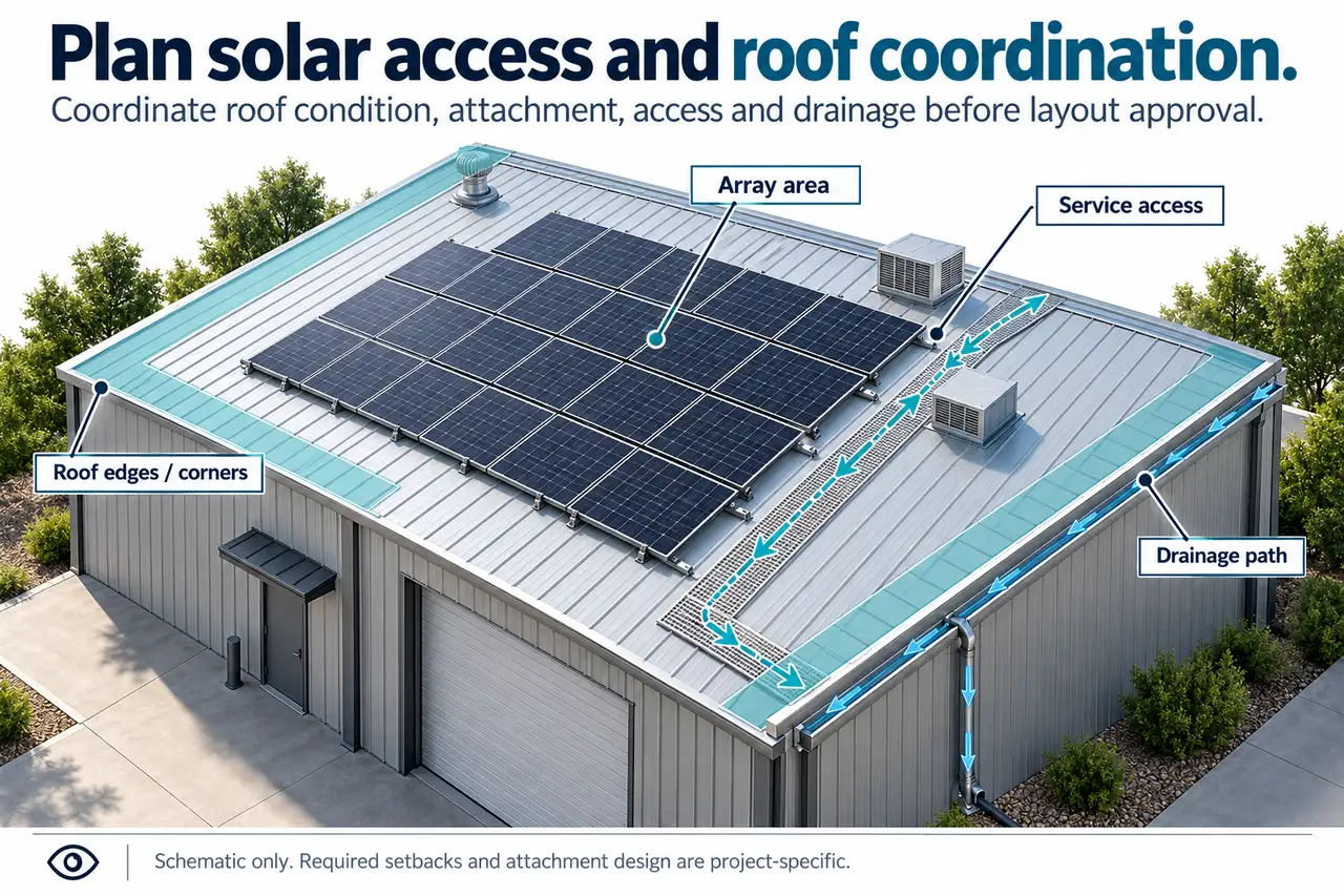
Compare the options against the same service event as well. Imagine that a roof area beside the array needs repair after installation. Identify who provides access, whether modules must be removed and which approved details must be restored afterward. This is a planning exercise, not a prediction of failure. It reveals differences in serviceability that a panel-count or energy-output comparison would miss, and it helps the owner decide which records and contractor responsibilities must be retained.
Plan installation, inspection and future access
Agree on site access, lifting, staging and protection of the existing roof before work. The installation contractor needs a plan suited to the actual building and applicable safety requirements. A roof layout diagram is not a fall-protection plan, and a service walkway drawn for illustration does not establish safe access by itself.
Specify how the installation is checked against accepted details. Identify relevant inspections, documentation and responsibility for deviations. If a roof detail differs from the assumption used in design, record the difference and resolve it rather than adapting the connection informally. The owner should receive evidence of the installed system, not only the original sales layout.
Plan recurring service around both the roof and electrical equipment. Identify how technicians reach required components and how drainage or roof repairs can be handled. Keep the relevant manufacturer maintenance instructions and contact information. Do not invent one universal inspection interval for all roof and solar systems.
Consider removal and restoration as a future project. If roof work eventually requires temporary array removal, what documentation will support that operation and what interfaces must be restored? Record the products and details now, while they are accessible. Future service becomes more difficult when no one can identify the attachment system or approved layout.
Use the steel building buyer's guide to integrate solar with the building scope from the start. Whether the array is installed immediately or later, preserve the design basis and interfaces. A genuinely coordinated solar-ready project identifies what has been designed and what remains a future review, rather than relying on a broad label.
Questions about solar on a metal building
Do nonpenetrating clamps eliminate engineering review? No. The clamp, seam, roof clips and supporting members still form a system. Obtain compatibility and structural evaluation for the actual arrangement rather than relying on the absence of a hole.
Is a lightweight array always acceptable? Weight alone does not establish the relevant attachment reactions, wind effects, snow effects or existing capacity. Have the complete proposal assessed. The result may support the installation without strengthening, but that conclusion must follow the evidence.
Can solar affect a roof warranty? It can raise review and approval questions that depend on the actual agreement and mounting. Obtain the issuer's written requirements before installation. Do not rely on a universal claim that all solar either voids or preserves coverage.
Should the roof be replaced before solar? Evaluate condition, necessary work, mounting compatibility and future service together. There is no universal roof-age cutoff in this guide. Compare the actual sequences and document the basis for the choice.
Can I add more panels later? Treat an expanded array as a revised proposal. Preserve the original design and installation records, then have the new layout and affected interfaces reviewed. A system approved for one arrangement is not an unlimited allowance for future equipment.