


Why the insulation label is only part of the answer
Metal building thermal bridging occurs where conductive materials create heat-flow paths across the insulated enclosure. Steel framing and attachments can let heat bypass insulation, so a batt's labeled R-value does not describe the performance of the completed wall or roof. A useful comparison must identify the assembly: insulation position, supporting members, attachment details, compression, junctions and openings. Buying a larger number on a bag is not the same decision as improving that assembly.
The PNNL guide to thermal bridging in steel-framed multifamily buildings describes how framing and attachments crossing the thermal enclosure reduce effective assembly resistance. Its building examples concern multifamily construction. The heat-flow principle is useful for a metal workshop, but its example details are not specifications for a pre-engineered building.
Start with the space you intend to condition. An entire heated shop, an insulated office inside a cold warehouse and a building used only occasionally have different enclosure boundaries. Mark that boundary on a plan and section before comparing insulation options. Otherwise a quotation can describe a roof insulation package while leaving the office perimeter, door interfaces or slab transition outside the comparison.
This guide uses a trace-the-path method: follow heat across each part of the enclosure, find where the insulation is interrupted, then ask what assembly evidence supports the proposed detail. The method does not calculate a correction factor or predict energy savings. It gives an owner a concrete way to compare proposals and recognize when the same insulation label is attached to materially different construction.
Follow the bridge through the actual construction
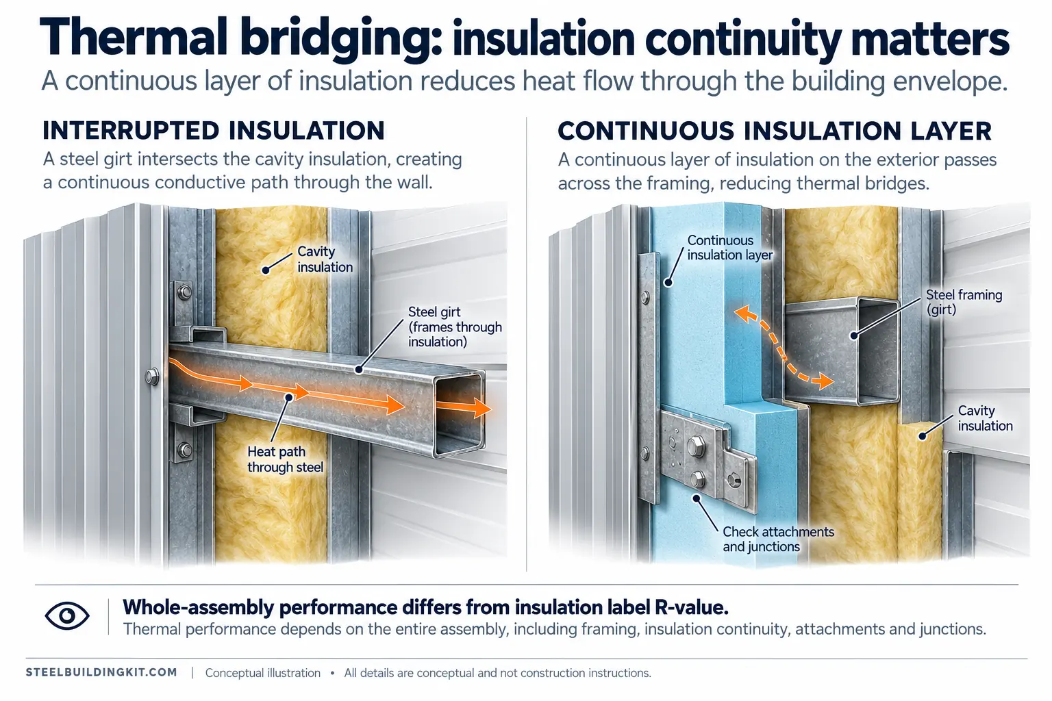
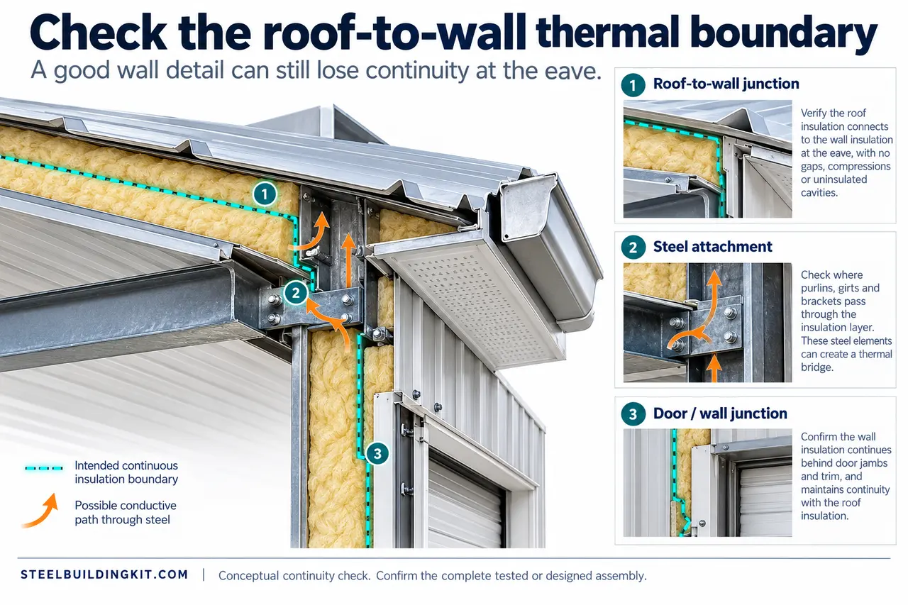
Picture a roof section from interior air to the outdoors. Identify the liner, insulation, purlin, roof attachment and exterior panel. Draw a line representing the intended thermal layer, then follow every material that crosses it. Some paths run through a framing member; others occur at an attachment or a junction between assemblies. The question is whether the proposed detail interrupts or accommodates those paths, rather than whether every component contains some insulation.
Repeat the exercise for a wall. A wall girt and its connection to the primary frame do not occupy the same position as insulation between supporting members. A door jamb may interrupt the insulation in a different way again. Make these locations visible on a marked detail. If a salesperson describes an option as a thermal break, ask which particular path it addresses and which paths remain.
Distinguish framing repetition from isolated details. A repeated support condition may influence a broad area; a roof penetration may affect one location. Both deserve design attention, but the evidence used to describe them may differ. Do not assume that one attractive central wall section represents every corner, base, opening and roof transition in the building.
Include construction sequence in the discussion. A continuous layer shown on paper must still be supported, fastened and joined in the field. Ask how installers will maintain its intended position while installing adjacent components. This is a practical buildability question, not an invitation to substitute unapproved spacers or reduce structural attachments. The structural and enclosure details need to work together.
Read the four control layers separately
Use four different pencil colors on the proposed detail: water control, air control, vapor control and thermal control. A material may perform more than one function, but that does not mean all functions are automatically continuous at its edges. Trace each layer across a lap, eave, wall base and opening. Where a line stops, request the connection detail rather than accepting a general statement that the building will be sealed.
Thermal bridging belongs primarily to the heat-flow discussion. Air leakage is a separate path through gaps and discontinuities. Vapor diffusion concerns movement through materials. Bulk-water management concerns rain and drainage. Keeping the categories separate makes it easier to understand a proposal: an air-sealing repair may improve one problem without eliminating a conductive connection, while additional insulation may leave a rain-entry detail untouched.
Ask how the insulation will meet the overhead door perimeter. A large, frequently opened door also affects operation, so a thermal improvement at the jamb does not establish the whole building's heating demand. Keep the detail and the operating pattern in the same brief without treating them as interchangeable. That helps an HVAC designer evaluate the complete space rather than an idealized closed box.
Record unknown layers explicitly. If an existing building has a liner hiding the supports, the original quote may not establish the current condition. Changes, repairs and later penetrations can alter continuity. Decide with an appropriate professional whether drawings are sufficient or targeted investigation is needed. An accurate sketch with one unknown is more useful than a polished drawing that assumes the missing evidence.
Compare cavity insulation and continuous layers
Cavity insulation occupies the space between supports. A continuous layer is intended to cross framing rather than stop at every member. These descriptions identify geometry, not a complete product specification. A real continuous-insulation system still has attachment points, edges and transitions that require design. Conversely, a cavity system can be part of a carefully evaluated assembly; its nominal label simply cannot represent every parallel heat-flow path by itself.
Compare alternatives using the same boundary and installed condition. Ask where the insulation sits relative to purlins or girts, whether the intended thickness is maintained, how it is restrained, and what happens at connections. If an option is described as a double-layer system, request a section that shows both layers and the supporting arrangement. Two stated product ratings do not establish the resulting whole-assembly value.
Continuous layers also need practical coordination. Additional thickness can affect trims, door details and accessory attachments. The supporting arrangement must accommodate the enclosure while satisfying structural requirements. Do not propose fewer fasteners or improvised nonmetallic washers to improve a sketch. Any change to the approved attachment system belongs with the designer and manufacturer who can evaluate the resulting loads and compatibility.
Decide what each option does well. A system may fit a new building because the roof and wall details can be coordinated before fabrication. A retrofit may be constrained by existing panels, access and service lines. A comparison should show those constraints alongside thermal evidence, repair access and installation sequence. It should not declare a universal winner from the material category alone.
Use assembly evidence instead of adding labels
R-value expresses resistance to heat flow; U-factor expresses thermal transmittance. For a simple, clearly defined assembly they describe related properties, but an owner should not combine miscellaneous product ratings to manufacture a whole-building number. The relevant boundary, included layers, framing effects and installation conditions must match the evidence being cited. Ask for the assembly identification and the basis of the stated performance.
| Quotation statement | Evidence to request | Comparison trap |
|---|---|---|
| Insulation has a stated R-value | Product data plus the installed assembly description | Treating a material rating as a roof or wall rating |
| System meets an assembly U-factor | Applicable test, calculation or accepted assembly reference | Comparing different framing, spacing or attachment conditions |
| Thermal break included | Detail showing its location, extent and connections | Assuming one treated path removes every bridge |
| Two insulation layers included | Section showing support and installed thickness | Adding nominal labels without evaluating the complete assembly |
If a supplier offers a tested assembly, ask whether your project matches the tested configuration or what accepted method addresses differences. Roof profile, supports and insulation arrangement should not disappear behind the phrase 'similar system.' You do not need to reproduce the engineering calculation yourself. You do need an explanation of why the evidence describes what will actually be purchased and installed.
Also distinguish code documentation from a comfort or operating-cost guarantee. Demonstrating compliance with the adopted energy requirements is a specific design task. Predicting how a shop feels or what it will cost to heat requires additional information about use, climate, controls and equipment. A credible proposal keeps those conclusions separate and states which one its supporting document establishes.
Understand comfort and condensation without overdiagnosing
Cold-weather condensation analysis by Building Science Corporation shows how exterior insulation can warm sensitive framed-wall surfaces, while indoor moisture conditions affect condensation risk. Its examples are not metal-building roof specifications. Use the principle to ask better assembly questions, not to copy an example thickness or promised surface temperature.
A cold band on an interior surface can be a useful clue, but the clue is not a complete diagnosis. Air leakage, missing or displaced insulation, a conductive support and surface measurement limitations may need consideration. Likewise, moisture near a support does not establish that the support is the only cause. An investigator should connect observations to the actual detail and operating conditions.
An infrared image is best treated as part of an evidence packet. Record when it was taken, the indoor and outdoor conditions, equipment operation and which surface was viewed. Ask the person interpreting it what patterns are meaningful and what other checks are needed. A colorful image alone does not establish a whole-wall R-value or prove that a proposed repair will stop condensation.
Separate the desired outcomes. You may want a warmer interior surface, lower heat transfer, fewer condensation events or more even comfort near workstations. Those goals overlap, but they are not identical acceptance criteria. Specify which outcome matters at each location. This makes it easier for the enclosure and HVAC teams to propose coordinated work and explain what can be observed after installation.
A hypothetical comparison of two workshop proposals
Imagine two proposals for the same newly conditioned workshop. Both name the same nominal batt rating. Proposal A shows insulation between supports and gives no eave or door details. Proposal B supplies an assembly section, identifies the support arrangement and provides a performance reference. This is an illustrative purchasing example, not a claim that one named system outperforms another.
Begin with completeness. Ask Proposal A for the same detail and evidence categories supplied by Proposal B. It may turn out to describe an acceptable evaluated system; the missing information is a reason to investigate, not proof of poor performance. Ask Proposal B whether its reference matches the actual roof profile, framing and installation. A well-presented document can still describe the wrong configuration.
Next compare junctions. Put the eave, wall base and overhead door side by side. Mark where the thermal layer changes direction and how attachments cross it. If one proposal includes a coordinated transition while the other leaves it to an installer, record that scope difference. The difference may affect who designs the detail and when it must be resolved, even before a performance comparison is possible.
Then compare deliverables. Will the contract identify the assembly, supporting evidence and installation details? Who checks substitutions? What photographs or inspections will document hidden work? These questions convert the discussion from a sales label to a reviewable construction scope. They also give the owner a way to recognize a later change that needs design review.
Finally make a conditional decision. Select an option only after the evidence fits the intended building and unresolved interfaces have an owner. If both options are adequately documented, compare the project-specific tradeoffs that remain: usable space, installation access, future repairs and coordinated cost. Do not invent an energy-payback figure to break a tie when the inputs for that calculation have not been established.
Coordinate the detail before it becomes expensive to change
Freeze the intended use and enclosure boundary early enough to inform openings, framing interfaces and mechanical design. A small conditioned room inside a larger building needs a different coordination drawing from a fully conditioned shell. Mark what will be installed now and what is only reserved for later. Future-proofing is useful only when the current scope makes the distinction clear.
Assign responsibility for assembly selection, structural attachment, condensation evaluation and code documentation. The same company may handle several tasks, but the tasks should still be named. If the insulation supplier depends on a detail from the building manufacturer, include that handoff in the schedule. Otherwise each party may reasonably assume another has resolved the interface.
Use a substitution rule in the project documentation. A proposed product change should identify which approved assembly assumptions it affects and who must review it. An apparently equivalent nominal R-value may not establish equivalence in vapor behavior, support, thickness or fire-related properties. Request a coordinated review rather than allowing the bag label to become the only acceptance criterion.
The steel building buyer's guide can help organize the broader purchase. Add a thermal-assembly schedule to that process: roof, wall, junctions, supporting evidence and responsible reviewer. Keep the scope specific enough that a final walkthrough can compare installed conditions with the agreed detail, rather than with a general promise of a well-insulated building.
Questions about thermal bridges and insulation ratings
Will thicker cavity insulation eliminate thermal bridging? It may change the assembly's heat flow, but it does not remove the metal path simply by making the adjacent insulation thicker. Ask for assembly evidence for the proposed change and consider how its moisture and installation implications are addressed.
Do screws make continuous insulation pointless? No single attachment observation establishes the value of an entire system. Attachments are part of the assembly that must be evaluated. The appropriate question is how the specified system accounts for its connections, not whether a drawing contains any metal at all.
Can I compare a wall R-value with a roof R-value? Only after understanding what each number represents. Product ratings, effective assembly ratings and whole-building performance are different descriptions. Keep the stated boundary and evidence alongside each value so you do not compare a material on one quotation with a complete assembly on another.
Does a thermal break guarantee no condensation? No. Condensation also depends on air moisture, surface temperatures, air pathways and operating conditions. A local thermal detail belongs in a coordinated enclosure plan. If the building is already wet, investigate the wetting mechanism before using a thermal improvement as the entire repair strategy.